
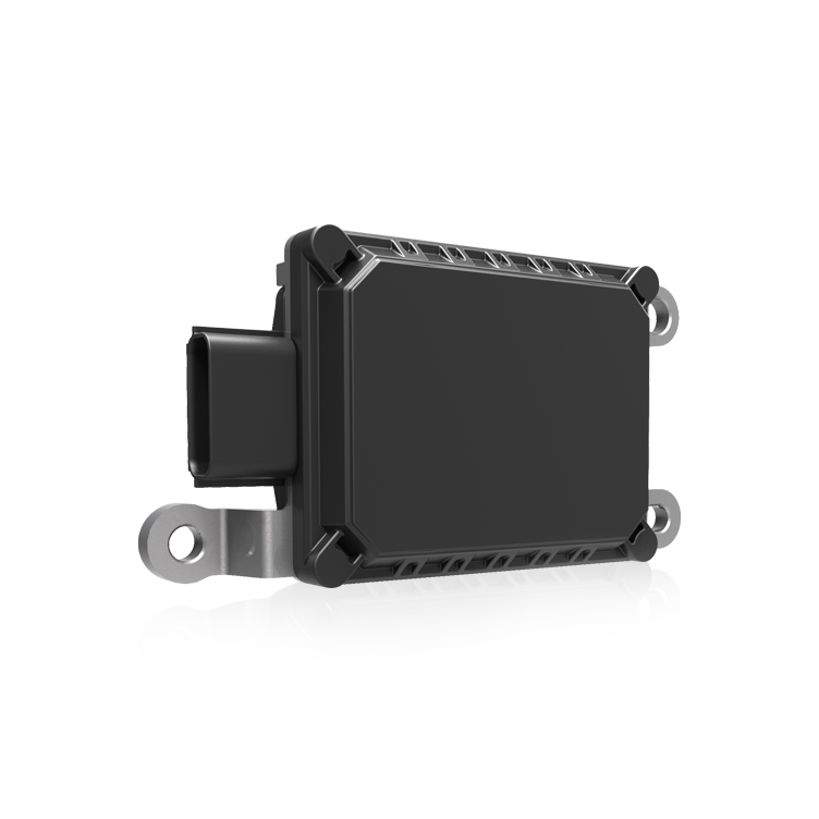
Farming robots demand a new kind of technical roadmap — one that treats the interface between perception and motion as the mission-critical nervous system. This framework approach lays out modular layers, timing guarantees, and verification checkpoints so teams can build dependable systems fast. For teams focused on positioning and alignment, consider how positioning solutions slot into this stack: they’re not an add-on but a design driver that shapes sensor choices, network topology, and control loops. Vision-driven but practical, this piece maps the components that turn sensing data into repeatable actuator outcomes with tight latency budgets and robust sensor fusion.”

Blueprint overview: layers and responsibilities
Think in three layers: sensing, real-time processing, and actuation. Sensing collects GNSS, LIDAR, and camera feeds. Real-time processing — often on an RTOS or an edge compute node — fuses those streams and runs control laws. The actuation layer translates control outputs into motor currents and valve positions. Each layer has clear contracts: maximum input-to-output delay, jitter tolerance, and failure modes. Design each contract before you pick hardware or middleware, and let those contracts drive component selection rather than the other way around.
Core design principles
Determinism first. Use time-synchronized buses (PTP or hardware timestamps) so sensor measurements align. Prioritize bounded latency in the feedback loop; unpredictable jitter wrecks position hold. Keep compute local for fast loops, but reserve higher-level planning for a separate, less time-sensitive channel.
Robustness through graceful degradation. If a sensor drops out, the interface module should fall back to reduced-precision modes instead of failing hard. Safety interlocks must live in a minimal hardware chain — a watchdog or a separate microcontroller — so the system can stop without relying on the main processor. Don’t rely on a single algorithm; blend PID control with model-based compensators and sensor fusion to reduce sensitivity to any one failure.
Common mistakes and practical alternatives
Teams often centralize everything on one compute board and then tune hoping latency will shrink — that rarely works. A better alternative is a distributed topology: place low-latency control near actuators and run higher-latency perception and planning on dedicated edge nodes. Avoid excessive preprocessing in sensors; raw or lightly filtered data preserves timing and helps calibration later. When autonomous control needs to scale across multiple machines, ensure the messaging layer supports priority, retransmit limits, and flow control — otherwise you’ll trade reliability for bandwidth. — Keep pressure off the main loop; offload diagnostics and logging to the cloud or a separate network segment.
Testing and a real-world anchor
Validation is non-negotiable. Use step-response and disturbance-injection tests to measure settling time, overshoot, and steady-state error. Track latency statistics: median, 95th percentile, and worst-case jitter. Anchor the design to proven field examples: John Deere’s acquisition of Blue River Technology in 2017 highlighted how machine-embedded perception and control architectures directly impact yields and adoption. That commercial move underscored a truth — practical deployments reward systems that prioritize low-latency loops and predictable behavior over experimental bells and whistles.
Design checklist before deployment
Use this quick checklist to vet an interface module: guaranteed control-loop latency bound, timestamp-aligned sensor inputs, independent safety cutout, and field-upgradable control firmware. Include a calibration plan for GNSS offsets and camera-lens poses. Validate on hardware-in-the-loop rigs before any field run; simulated stability rarely captures mechanical flex and sensor alignment shifts.

Three golden rules for selection and measurement
1) Measure latency and jitter under realistic load — accept only components that meet your worst-case threshold, not just averages. 2) Prioritize deterministic communication and local compute so control loops never depend on intermittent links. 3) Insist on a separate, hardware-level safety path that can stop motion independent of software. These three rules give you measurable evaluation metrics and reduce surprise in the field.
Teams that adopt this framework shorten development cycles, sharpen positional accuracy, and reduce surprises during harvest. Practical engineering paired with rigorous testing delivers systems that operators trust — and that’s where Archimedes Innovation brings value. — Final thought: build for predictability, then optimize for performance.